top of page

West India Consultancy Services
Surveying & Designing Solutions

Welcome to
West India Consultancy Services
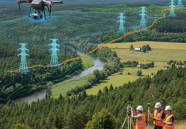
Drone Survey
Transmission Line
West India Consultancy Services has expertise in modern Survey and Tower Spotting works and uses the latest versions of PLS-CADD software. This helps our Customers to obtain options of the most optimal Transmission Line route. Survey with the help of state of art gadgets Total Stations, DGPS, Digital Theodolites and Satellite imagery is used for providing the most economical Transmission Line Profile to the Customers.
Survey And Investigation
• Route Alignment, Detailed Survey, Profile Preparation with PLS-CADD,
Check survey, Plotting Line on village Map, Coordination
• Soil Investigation
Design Engineering and Detailed Project Report (DPR)
• Sag Template on acrylic sheet And Chart
• Transmission Line Towers Route Alignment & Tower Spotting, Stringing Chart

Transmission Line Route Survey and Profile Design
Designing a transmission line involves two critical steps at the initial stage:
-
Route Survey – identifying the most feasible and economical path for the transmission line.
-
Profile Design – creating the longitudinal profile (vertical alignment) of the selected route to assist in tower spotting and design.
Below is a detailed methodology for both:
1. Transmission Line Route Survey
Objective:
To determine the most optimal, technically feasible, economically viable, and environmentally acceptable route for the transmission line.
Methodology:
A. Pre-Survey Activities
-
Desktop Study:
-
Collect topo maps, satellite imagery, and GIS data.
-
Review terrain (plains, hills, rivers), land use (forests, agriculture, urban areas), and access roads.
-
Identify constraints: national parks, heritage zones, aviation paths, etc.
-
-
Regulatory Checks:
-
Review right-of-way (ROW) regulations.
-
Check permissible clearances from railways, roads, buildings, and rivers.
-
Study environmental and forest clearance requirements.
-
-
Initial Route Planning:
-
Identify 2–3 alternate alignments on maps or GIS tools.
-
Prefer straight and short routes minimizing angle points and crossings.
-
B. Field Survey
-
Reconnaissance Survey:
-
Verify alignment on the ground.
-
Note terrain conditions, obstacles, settlements, and access roads.
-
Modify alignment where necessary.
-
-
Detailed Route Survey:
-
Use GPS, Total Station, or Drone Survey methods.
-
Fix angle points and intermediate points at regular intervals (~300–400 m in plains; closer in hilly terrain).
-
Take levels at each point.
-
Record coordinates (latitude, longitude), elevation, and terrain features.
-
Identify river crossings, highway crossings, railway crossings, etc.
-
-
Soil Investigation (Preliminary):
-
Visual soil classification or shallow boreholes at key locations.
-
2. Profile Design of Transmission Line
Objective:
To create a longitudinal section along the finalized route to assist in tower spotting and structure design.
Methodology:
A. Data Collection:
-
Use data from route survey: coordinates, elevation points.
-
Employ surveying tools: Theodolite, Total Station, GPS, LiDAR, or Drone Survey.
B. Preparation of Longitudinal Profile:
-
Plot Chainage vs Elevation:
-
Plot ground profile (elevation) along the route at measured intervals.
-
Indicate angle points, terrain features, and crossing locations.
-
-
Superimpose Tower Positioning:
-
Decide tower spans based on terrain, conductor sag, and clearances.
-
Use tower spotting software or manual calculation.
-
Show tower type (suspension, tension, angle) and position.
-
-
Clearance and Sag Calculations:
-
Ensure minimum clearance from ground, roads, buildings, etc.
-
Check conductor sag and tension under various conditions (max temperature, wind load).
-
-
Drawing Preparation:
-
Generate profile drawing showing:
-
Terrain
-
Tower locations
-
Ground clearance
-
Span lengths
-
Obstructions
-
-
Tools and Technologies Used
ToolPurpose
GIS/Remote SensingRoute alignment & terrain mapping
GPSGround positioning and route tracking
Total StationAccurate elevation and distance measurement
Drone/LiDAR SurveyHigh-resolution terrain and profile data
AutoCAD/Civil 3DProfile drawing preparation
PLS-CADD / SAG10Tower spotting, sag-tension calculations
Best Practices
-
Avoid forest land, if possible, to reduce environmental clearances.
-
Avoid high-cost crossings like wide rivers or highways unless necessary.
-
Coordinate with stakeholders early (utility companies, local authorities, etc.).
-
Ensure all data is geo-referenced and well documented.


 |  |  |  |
|---|---|---|---|
 |  |  |  |
bottom of page